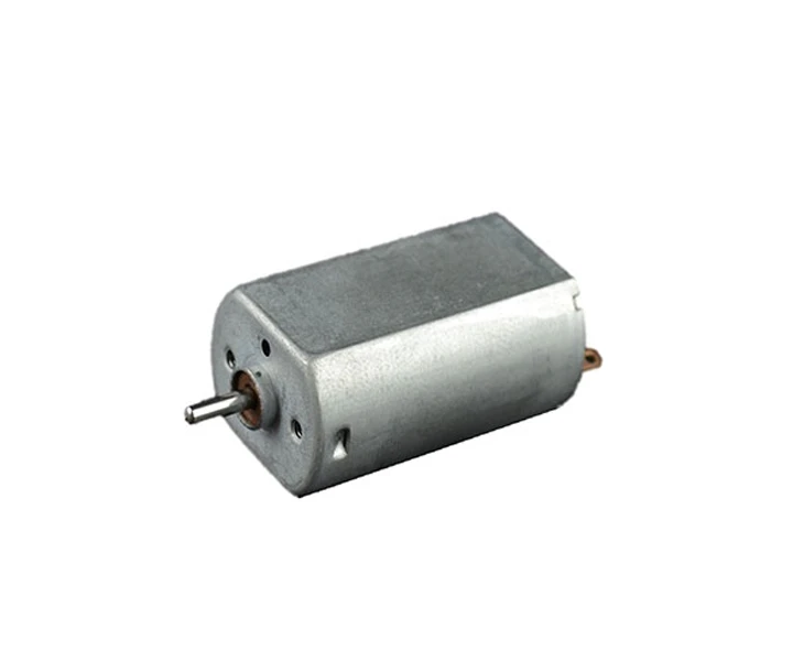
EBenefit from quality and cost savings in tandem with this low-cost PMDC motor. Available sizes are 16 mm, 20 mm, and 24 mm motor diameters. Fit with precision components, including high-efficiency bearings, preloaded ball screws, encoders, and custom designs.
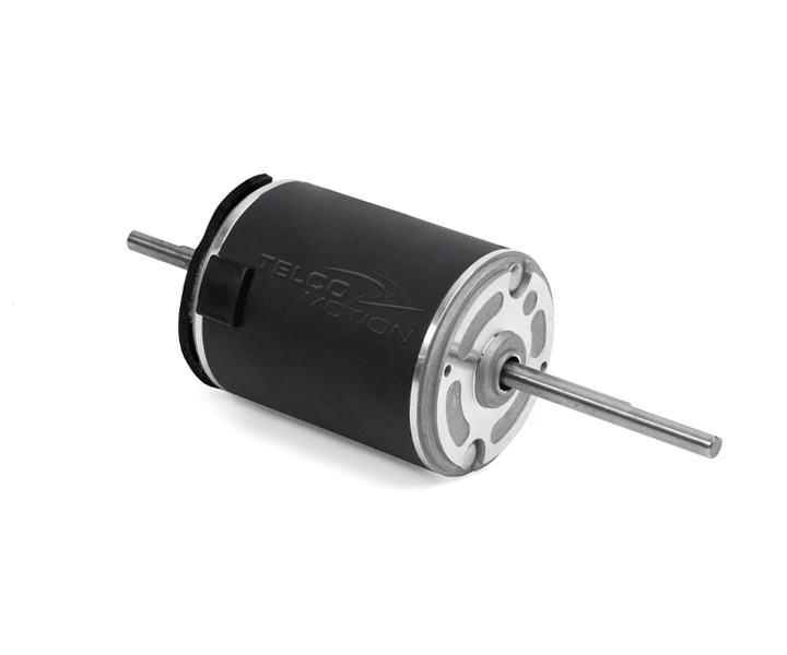
Our best-selling gearmotors flaunt advanced design and robust construction. They are powerful, reliable, and built to last. Choose from a broad range of sizes, from small to large, with different windings for high torque applications.
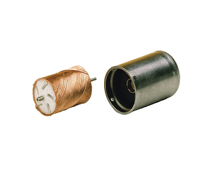
With an exceptionally fast response time and compact design, these coreless motors deliver special functionality, highly valued in key medical applications.

